


Before starting this project, I researched to check if anyone had made a similar project in case I could use some aspects of their designs. I found similar boxes, but most of them had a 1-meter layout instead of the 3-meter design that my client had emphasized.
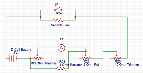
The main idea that I gleaned from these designs was the resistance meter being an analog-style ohmmeter based on an ammeter wired in parallel with a 1 ohm resistor and with a 1.5 volt battery, adjustable with 5Ω, 10Ω, and 100Ω potentiometers. Below is a schematic (provided by my client) for a box that tests lines A-A, A-B, B-B, B-C, C-C, and A-C independently on one meter. I used a similar meter and buzzer design.

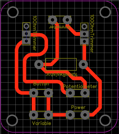
For the ohmmeter, I found a circuit layout from The Armorer’s Store and reversed engineered it using the components in order to come up with my own schematic. Below are my own schematic and circuit layout. Later posts will outline my circuit design process.
The rest of my research consisted of checking the rules and regulations governing resistance limits for equipment (1Ω for body and mask cords, 2Ω for weapons, 5Ω for the lame) and checking the grounding line for weapons (the C line). Click here to view the 2017 FIE Handbook for all fencing rules.
Stay tuned for more!
—
