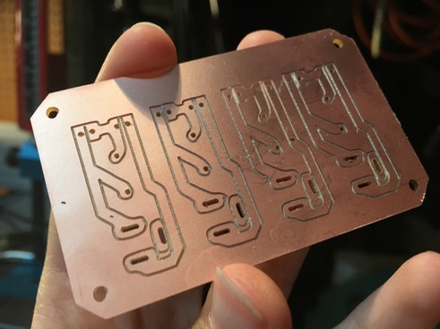

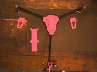

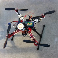
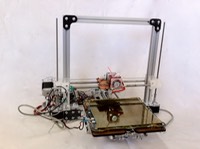


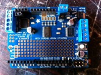

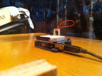
Now with the X-Carve in my toolbox, I was able to prototype circuit boards much more rapidly than the last method (etch resisting). This way, I was able to test and revise much more quickly, speeding up my process significantly. Below, I depict multiple different projects as examples.
There were three stages to making a board with the X-Carve:
1. Designing the PCB
Using easyeda.com and a similar design that I had prototyped earlier, I made a schematic and a PCB. Below is a timelapse of me designing on easyeda.com.
I then exported the PCB as an SVG.
2. Setting up in Easel
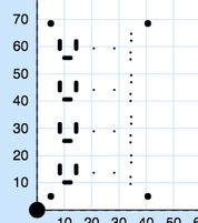
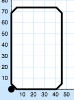
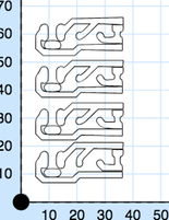
In order to cut the piece, I broke the PCBs into 3 parts: the trace outlines, the holes, and the board outline. Using “Select Same > Fill and Stroke”, I isolated each part.
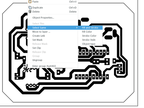
Next, I would trace the bitmap path of everything left after the selection and put that file into Easel in the same orientation.
3. Cutting the PCB
Since each design was laid out with the same orientation, scale, and homing position, I could maintain the same homing position between the three cuts and be sure that approximately the same board was being cut.
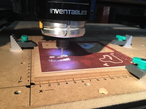
To cut the traces, I used bits from Inventables’ PCB milling set. To cut the holes, I used bits sub-1mm from the drilling set, and to cut the board outline, I used the 1/8” fishtail bit.