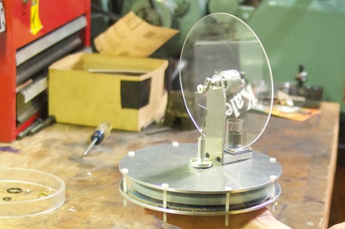
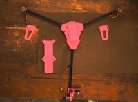
Now that all the parts were completed, I began to assemble. During assembly, I had to cut additional parts to size, such as the nylon and brass screws and the steel connectors which go from the displacer to the crankshaft and from the flywheel hub to the piston assembly. I also cut small nylon spacers that fit around bearings on the lathe.
I started by test fitting that the ring and the two plates fit together by screwing them all together with nylon screws.
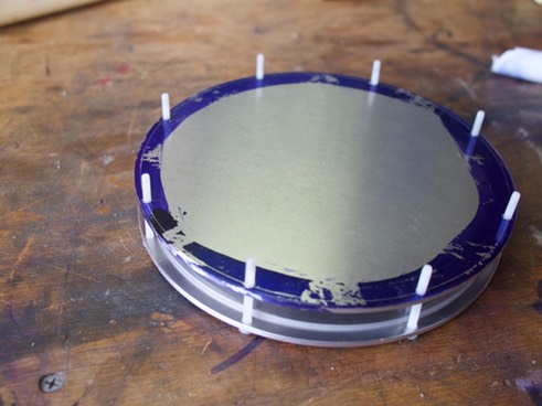
Next, I added the base block and bearing plate to the top plate.
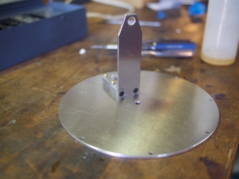
I added the chamber ring, the displacer block, and the bottom plate with the nylon screws again. In addition, I glued the bearing housing into position.
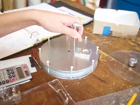
Next, I attached the displacer bushing with brass screws. In order to have access to the screwholes for the bushing, the bearing plate and block had to be removed.
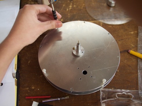
I epoxied the chamber in which the piston slides into a ring which fits onto the block. I added the block, tube, and plate back onto the top plate.
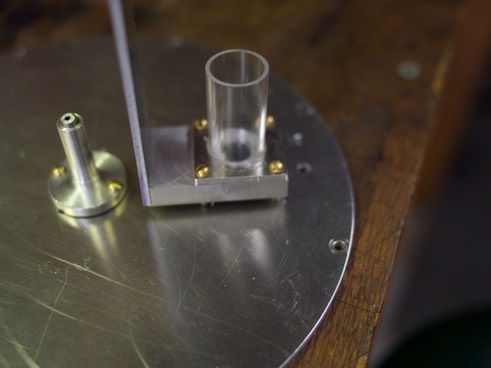
I added the crankshaft along with bearings in the bearing housing. I slid the flywheel and flywheel hub over the crankshaft, and tightened everything.
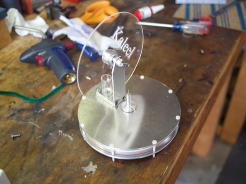
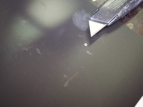
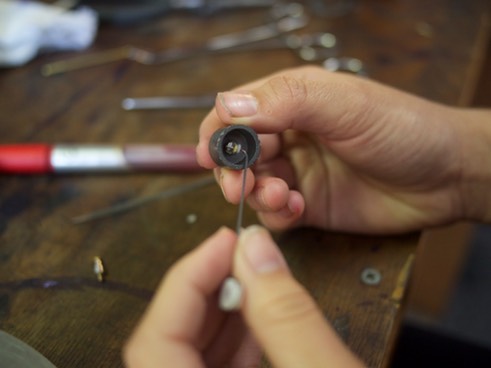
I now made the nylon spacers. I started with a long cylinder on the lathe, cut a hole through and added a notch (which the wire will fit into). Then I cut off the spacer (I held the tip of a pencil near the hole to catch the spacer.) I also cut retaining collars for the wire (pictured).
I estimated a length of steel rod then cut with steel cutters. Using two pairs of pliers, I wrapped the rod around the spacers. I also added a Z-bend in the center of the wire so the length, from end-to-end, was adjustable.
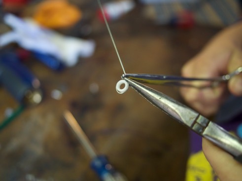
I added a hook at the end so the wire would fit into the piston assembly.
Once I added the wires, voilá! The Low Temperature Differential Stirling Engine was done. Now, it was time to troubleshoot.
