


X-Carve Build Timelapse
Here is a timelapse of my Inventables X-Carve 750x750mm build. The entire build was about 5 hours over the course of two days. Calibration and adjustment took about an hour. Initial software setup was easy and comprehensive. I used this X-Carve to cut circuit boards for the KFETS.
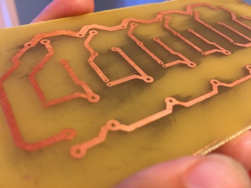
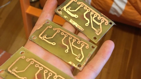
KFETS Part 6: Circuit Boards 2
Now with the X-Carve in my toolbox, I was able to prototype circuit boards much more rapidly than the last method (etch resisting). This way, I was able to test and revise much more quickly, speeding up my process significantly. Below, I depict multiple different projects as examples.
There were three stages to making a board with the X-Carve:
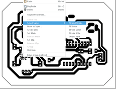
1. Designing the PCB
Using easyeda.com and a similar design that I had prototyped earlier, I made a schematic and a PCB. Below is a timelapse of me designing on …
KFETS Part 5: Specialty Parts
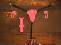
From the outset of the KFETS project, my client knew that he wanted it to be as sturdy and unbreakable as possible. To ensure this, I searched for “milspec” (military specifications) parts. The two parts which I focused on were the ones that would endure the most abuse: the mode switcher and the central switch.
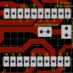
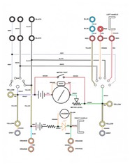
Above: the central switch in my PCB and schematic:
I designed the central switch to be a 4-pole, 3-position rotary switch. Any 4p3t switch with military specifications available online was out of my price range. …
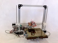
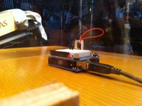
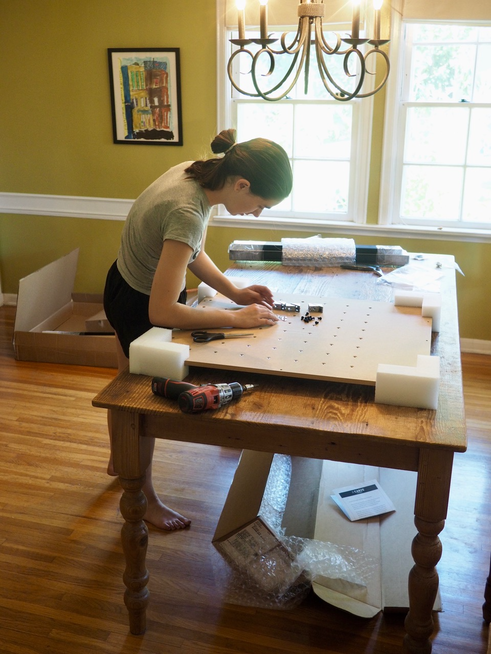
X-Carve Build
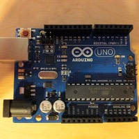
To improve the quality of my circuit boards and the precision of the panel, I knew I’d have to go digital. We determined that a CnC would be the best option for this, and after some research, we decided on Inventable’s X-Carve 750x750.
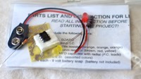
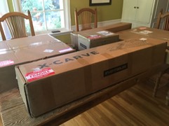
The parts shipped in multiple boxes. The boxes were labeled with their contents and this helped majorly in organization during assembly.
Click here for full instructions on how to build or buy an X-Carve.
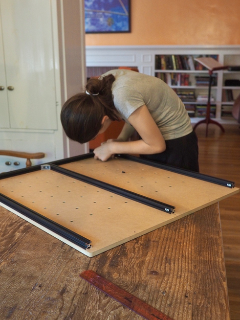
The entire build took me a Friday and by Saturday night, I had my first cut.
…
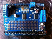
KFETS Part 4: Circuit Boards 1
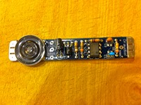
The short lights in my first prototype were connected by a circuit board, as were the meter panels displaying resistance. These circuit boards were the first I’d ever made, evident in the uneven hacksaw cuts on the side :), but were a good foray into the world of circuit board making.
After prototyping, I knew which connections I wanted, I had drawn rough schematics on paper while wiring. I finalized my initial schematics. The next step was to digitize my schematics and print a circuit to transfer. …
KFETS Part 3: Prototyping 1
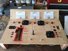
The stages between research and a final product can take a long time, with many iterations and prototypes in between.
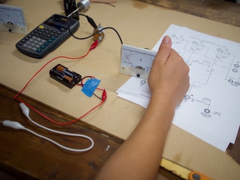
After obtaining all the parts, I connected everything with jumper wires and a breadboard for PCB-mount components.
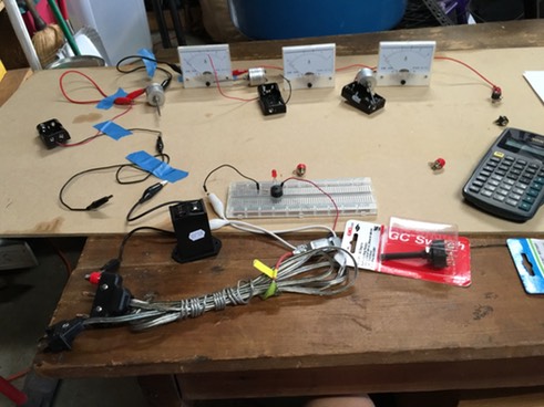
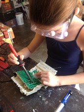
After I was satisfied with how everything was working, I realized that I needed to make circuit boards to mount buzzers (responsive to shorts) and to mount the parts that run the meters. So, I learned how to make boards:
The first method I learned was acid-resist PCBs, which is how the two above were made.
…
EngX 2018

On February 24, 2018, the USC Viterbi School of Engineering and the Armani Labs are holding their annual EngX event in the Epstein Family Plaza at the university. Presenters include USC students along with JPL and USC’s Insitute for Creative Technologies! For more information, visit the EngX website here.
Making Basic Packages in EasyEDA
While making the KFETS, I used the free EDA (Electric Design Automation) software EasyEDA in order to lay out my schematics and circuit boards. Recently, I encountered an issue which I thought could be best resolved by making my own part. It took a little while for me to figure out how to do this, and in the end I figured out that I had to make a basic “package” including a schematic (Schematic Lib) linked to the pad layout for a circuit board (PCB Lib). I recorded the video below to explain how to create these packages.…
KFETS Part 2: Research
Before starting this project, I researched to check if anyone had made a similar project in case I could use some aspects of their designs. I found similar boxes, but most of them had a 1-meter layout instead of the 3-meter design that my client had emphasized.
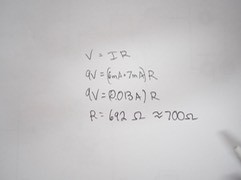
The main idea that I gleaned from these designs was the resistance meter being an analog-style ohmmeter based on an ammeter wired in parallel with a 1 ohm resistor and with a 1.5 volt battery, adjustable with 5Ω, 10Ω, and 100Ω potentiometers. …
DTLA Mini Maker Faire

Had so much fun today presenting along with 45 other makers/groups at the Downtown Los Angeles Mini Maker Faire at the Los Angeles Central Library! With over 1500 in attendance the Faire was a total success. There were so many cool projects and people. I had such an amazing time!
