


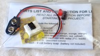


The short lights in my first prototype were connected by a circuit board, as were the meter panels displaying resistance. These circuit boards were the first I’d ever made, evident in the uneven hacksaw cuts on the side :), but were a good foray into the world of circuit board making.
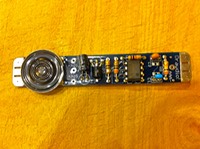
After prototyping, I knew which connections I wanted, I had drawn rough schematics on paper while wiring. I finalized my initial schematics. The next step was to digitize my schematics and print a circuit to transfer. After transferring the design onto the copper clad board I etched the circuits with ferrochloric acid. Next, I used my drill press to drill out the component holes.
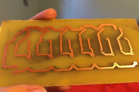
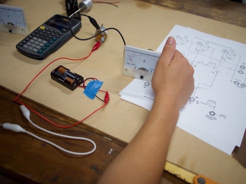
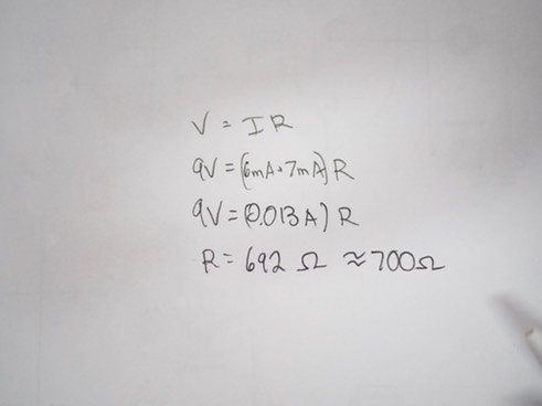
I soldered together the board then connected the relevant points to a rotary switch in the middle of the board and the 6 input sites to these boards. At this point, I had to do some troubleshooting.
Due to the way I had wired the board to make all of the short lights and buzzers run off of one battery (possible, but I didn’t know how to do it), the circuit naturally shorted itself. I tried using an X-Acto knife to break the copper tracelines and surface-mounted in diodes. When this didn’t work, either, I ended up only wiring the non-cross-shorting short-testing circuits. Thus, the prototype was only partially functional, but served enough purpose that it was useful.
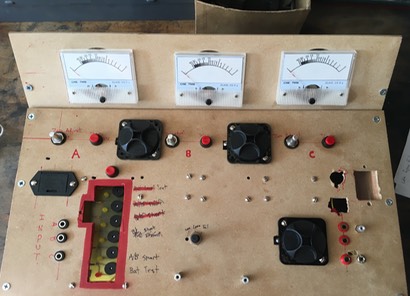
To optimize the modular style with which I had designed the boards, I used screw terminals to connect all variable connections, which came in handy for maintenance and troubleshooting.
