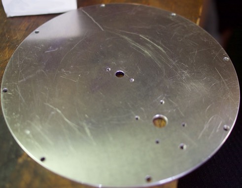
The next parts I made for my Stirling engine were the top and bottom plates. These plates are structural, where many assemblies are attached, though they also function as a conductor for the heat source.
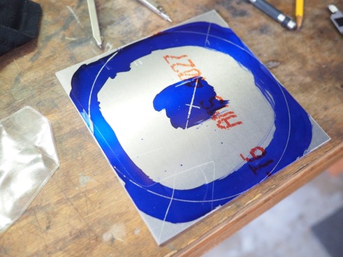
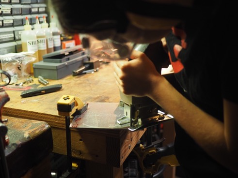
I layed out the circles on 1/4” thick aluminum square with layout fluid and a protractor, then cut them out with a jigsaw:
Next, I cut a circle out of scrap wood with roughly the same dimensions and mounted it on a plate to attach to my lathe:
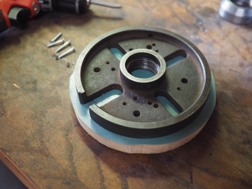
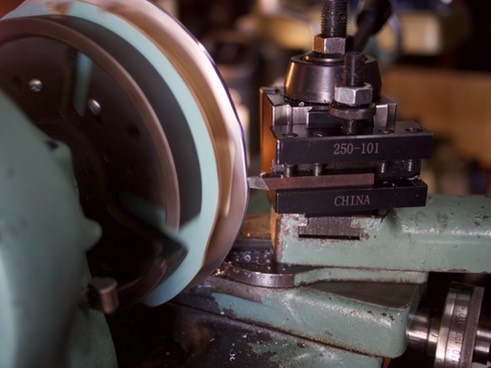
To clean up the edge of the aluminum circle, I centered and mounted it on the wooden arbor with double-sided duct tape (after I was done I removed the aluminum by heating up the adhesive with a blow torch so it would become looser).
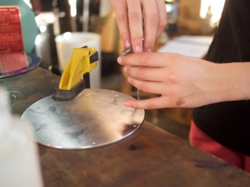
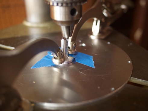
I layed out the edge holes and cut them on the drill press. The holes were through-hole (meaning that the bolt went through) on the top and threaded (meaning that the bolt screwed in) on the bottom plate. I first cut with the bit for the inner diameter of the screw-hole on all of the plates, which I had taped together. I cut all the holes, then separated the plates to deal with them individually. Here I am tapping the holes to thread them on the bottom plate.
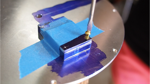
Next, I cut the base-block holes on the top plate using the base block as a guide. Then I tapped the holes in the top plate. Here I am testing my threaded hole with a screw:
Finally, I cut the center hole, the pressure release hole (and tapped it), and cut the holes to attach the displacer bushing, which I used as a guide:
The plates were finished!
